

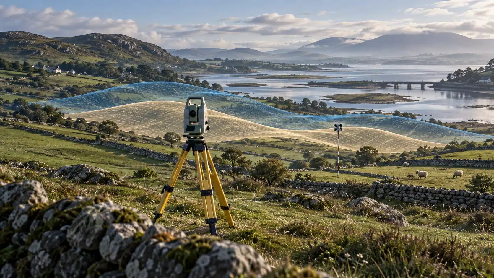
The same site, two convincing answers
Hypothetical example. An engineer opens a topographic survey beside a newly delivered drone point cloud. Both show the same road, boundary wall and drainage covers. Each dataset looks internally consistent, yet the surfaces sit at different levels. A third drawing, prepared for setting out, appears rotated relative to both. Nothing in the filenames explains why.
It would be premature to decide which survey is wrong. One might use a national grid, another a local construction grid. Their heights might refer to different surfaces or have been calculated with different model versions. Alternatively, the discrepancy might come from fieldwork, processing or a real change on site. The references must be established before the measurements can be compared fairly.
The distinction between precision and accuracy helps. Precision concerns how closely repeated measurements agree under stated conditions; accuracy concerns agreement with a true or accepted reference value. Repeating the same result does not establish that its reference is appropriate. These concepts are distinguished in the International Vocabulary of Metrology and its definition of precision.
In the hypothetical example, a useful first request is therefore the coordinate specification and control record, rather than a replacement drawing. The practical issue is whether the datasets describe the same features in compatible references, with sufficient evidence for the proposed use. The title’s two accurate surveys can only be understood in that qualified sense: each may meet its own brief while the combined model still needs reconciliation.
Irish Grid, ITM and the grid built for a project
A coordinate reference system gives numbers their spatial meaning. An easting and northing need a defined origin, orientation, units and relationship to the Earth. Changing that framework changes the coordinates that describe a location; it need not mean the location itself has moved.
Irish Grid and Irish Transverse Mercator, or ITM, are distinct projected systems. Tailte Éireann’s mapping glossary explains that ITM adopted the GRS80 ellipsoid and a different false origin from Irish Grid. An ellipsoid is a smooth mathematical approximation of the Earth’s shape; a projection expresses positions on a flat grid. The similar-looking numerical format is not evidence that the systems can be interchanged.
A local project grid may instead be aligned with a building or construction axis. That can make design dimensions and setting out easier to handle, but its relationship to national coordinates must be documented. The SCSI guide to map projections and scale factor explains the associated trade-off: coordination with neighbouring information versus convenient construction geometry.
Grid distance and measured ground distance also require attention. Flattening a curved reference surface introduces projection scale effects, while site elevation matters when reducing measurements. A national grid is not automatically a ground-distance grid. Neither an unexplained scale adjustment nor a visual rotation is an adequate project definition.
GNSS, the family of satellite positioning systems that includes GPS, is a measurement method rather than one universal export format. EUREF’s explanation of ETRS89 shows why reference-frame identity matters: the European system is tied to stable Europe. A file described only as GPS or WGS84 leaves questions at engineering precision, including its actual realised frame and, where relevant, coordinate epoch.
Four ways to describe a position
Read the horizontal coordinates and the height reference as separate parts of the record.
Irish Grid
Projected eastings and northings in metres; traditional all-island mapping grid.
Height reference must be stated separately.
Identify the Irish Grid CRS, source control, vertical datum and any transformation used.
Irish Transverse Mercator (ITM)
Projected eastings and northings in metres, based on ETRS89.
ITM alone does not specify the height datum.
Record the horizontal CRS, vertical datum, model version and independent check points.
GNSS latitude / longitude
Angular coordinates; frame/realisation, epoch and angular format matter.
A GNSS ellipsoidal height is not automatically a national-datum level.
State the reference frame, correction service or processing basis, epoch when relevant, and height conversion.
Local project grid
Project-defined origin, orientation and scale; document the units.
Local project zero or an explicitly linked national datum.
Supply the control schedule, transformation, valid extent and the link to the height datum.
A height is always above something
The word ITM on a drawing describes its plan reference; it does not, by itself, explain every Z value. A horizontal position and a height need compatible but separately identified references. An apparently correct plan overlay can therefore conceal a vertical disagreement.
An ellipsoidal height is referenced to the mathematical ellipsoid. An orthometric height relates to a gravity-based vertical reference, commonly described through a national height datum. As Ordnance Survey’s explanation of GNSS positioning makes clear, the satellite measurement is geometric: it does not independently determine gravity-related height. Survey equipment may nevertheless display an orthometric result after software applies a model.
The familiar relationship is H ≈ h − N: orthometric height H is obtained from ellipsoidal height h using a compatible geoid separation or height correction N. The FIG Reference Frames in Practice Manual, second edition, page 23 describes the model being evaluated at the point’s position. This is why a single remembered number is not a general conversion method for Irish heights.
A datum and a model are related but different things. Malin Head identifies a height reference used in Ireland; OSGM15 provides a model for connecting suitable satellite-derived heights with the relevant datum. SCSI’s survey specification, section 2.3, addresses the height datum separately from the plan grid. A deliverable should also explain any local reference, such as a building floor adopted as a project zero, rather than leaving it to inference.
The conceptual cross-section below separates the terrain, ellipsoid and gravity-related reference. Their spacing is deliberately exaggerated and represents no measured site. Its purpose is to show why changing the reference changes the reported height, even when the physical point remains where it was.
For a practical handover, ask which height is in the file, which model produced it, and how it was checked. Those questions apply to a single spot level just as much as to millions of points in a terrain model.
One point, several height references

Dark uneven line: ground, with the common point marked.
Short navy dashes: arbitrary project zero.
Blue curve: idealised geoid / gravity-related reference.
Long navy dashes: reference ellipsoid.
h, left: ellipsoidal height to the point.
H, upper centre: gravity-related height.
N, lower centre: geoid–ellipsoid separation.
Right arrow: height above project zero.
Conceptual, not to scale or measured. Arrow directions are simplified: the ellipsoidal normal and gravity direction need not coincide. A national height-correction model also fits the adopted datum.
A new label does not transform the coordinates
Assigning a coordinate system tells software how to interpret existing numbers. Transforming coordinates calculates the numbers needed to express the same physical positions in a different system. Confusing the two can give a file a reassuring label while making its spatial interpretation incorrect.
The distinction is explicit in QGIS’s Assign projection documentation: the geometry is retained and a different reference is assigned. Its Reproject layer operation instead transforms the geometry. This is a useful software example, not an instruction that every survey should be processed in that particular application.
Relabelling can be appropriate when a file’s coordinates are sound but its reference metadata is missing or wrong, provided the original system is independently established. It is not a substitute for conversion. Trying different labels until an outline falls near the expected road may suggest a hypothesis; it cannot establish the provenance or accuracy of the result.
A genuine transformation needs a known source and target, suitable operation parameters and any required correction grids. Horizontal and vertical steps may be separate. PROJ’s technical documentation explains how coordinate operations can be combined into a processing chain. Successful execution alone does not show that the chosen chain is appropriate for a particular dataset.
For Irish work, start from the resources identified by Tailte Éireann’s Geodetic Services. Ordnance Survey also states that its Grid InQuest II resources include the Irish polynomial transformation and OSGM15 models. GB’s OSTN15 horizontal transformation should not be assumed to be the Irish Grid-to-ITM operation.
What the 2016 height-model change actually shows
The joint OS, OSi and LPS paper published in 2016 documents the OSGM02-to-OSGM15 update. OSGM15 is a fitted height-corrector surface, commonly called a geoid model. Table 6, on PDF page 5, reports historical root mean square differences of 93 mm for Malin Head and 18 mm for Belfast.
Root mean square, or RMS, means squaring the differences, averaging them and taking the square root. It summarises their magnitude without retaining their sign. A larger RMS does not tell a reader whether a particular old level should be raised or lowered.
The chart excludes the table’s separate accuracy measure. Neither bar is a current survey error, guaranteed tolerance or site correction. The paper describes spatial variation; these figures must not be applied as uniform offsets.
When older and newer surveys meet, inspect their processing history before interpreting a level difference as movement. A revised model can change a calculated height without the ground moving or the earlier survey failing its original specification.
The same landscape. A revised height model.
OSGM02–OSGM15 RMS differences, millimetres.
Malin Head
Belfast
0 mm
100 mm
Not survey accuracy, signed corrections or uniform local offsets.
A seamless model can still hide different evidence
Consider another hypothetical handover. A utility drawing, a topographic surface and a drone point cloud have been transformed into an agreed project reference. Their common kerb line now aligns. This resolves one coordination question, but it does not establish that every line in the combined model was measured in the same way, at the same time, or to the same standard.
A utility line may represent a record interpretation, a detected route or a directly observed feature. Its position in a common grid does not improve the underlying evidence. The HSA’s Code of Practice for Avoiding Danger from Underground Services, section 7.4 explains limitations of plans, including changed reference features and unrecorded services. Coordinate reconciliation therefore cannot substitute for the investigations and safe working arrangements required before excavation.
A point cloud needs a similar separation between appearance and evidence. Dense coverage can make a surface visually persuasive without answering how it connects to control. The useful questions concern the delivered reference, what was checked independently, and whether vegetation, water or obscured areas affected the intended terrain representation. They should be answered in the survey’s method and quality information, rather than guessed from point density.
For setting out, the recipient also needs to know whether the design uses national grid distances or an agreed project treatment of scale. The SCSI scale-factor guide explains why mixing mapping and construction conventions requires care. A drawing can align on screen while dimensional assumptions remain unresolved.
A useful editorial principle follows from these examples: integration should preserve the distinctions needed to judge the information. Keep capture dates, source types and limitations attached to the relevant datasets. Combining files is not a reason to erase the differences between an observation, an interpretation and a design instruction.
From compatible files to a defensible handover
A repeatable workflow starts by preserving the originals and defining the intended use. The tolerance needed for an overview map may differ from that needed for a drainage tie-in or setting out. Acceptance should follow the project brief, with horizontal and vertical requirements stated separately.
Next, inventory each dataset. Record the horizontal system, units and axis order; the height type, datum and model version; the survey and processing dates; the control references; and any supplied transformation. Include the reference-frame realisation and coordinate epoch where relevant. Record an unknown as unknown until evidence resolves it.
The SCSI Measured Surveys of Land guidance, sections 2.3–2.12 treats grids, heights, transformations and control as linked parts of the specification. It calls for checking pre-existing control information and providing records of the resulting network. A filename is no substitute for that documented connection to identifiable points.
Select and record the required operation, then test it on suitable known points before processing an entire delivery. Where a transformation has been fitted to control points, validation should include other suitable points, rather than relying solely on the observations used to obtain the fit. The FIG manual’s discussion of testing and network reliability, pages 36–38 explains why residuals and checks require considered interpretation.
If the tests disagree, investigate before merging. A uniform offset, a rotation or a discrepancy that varies across the site can help frame the investigation, but none identifies its own cause. Check the source definitions, operation, control condition and capture history. Repeated unexplained adjustments make a model harder to audit.
Finally, issue a short transformation and verification record with the coordinated data. State what was received, what changed, how the result was checked and what limitations remain. Preserve both the source and delivered versions. The next engineer should be able to reproduce the reasoning without relying on the person who happened to perform the import.
From incoming file to coordinated delivery
Identify the source references
Read each file’s horizontal CRS, height datum, units, model version and processing record. Unknowns stay visible.
Choose the conversion or transformation
Define the target reference and select the documented operation, model and valid area. Keep the original data.
Check common control independently
Compare suitable points distributed across the site, including height checks. Reserve checks that did not determine the fit.
Review residuals and limitations
Look for consistent shifts, rotation, scale or tilt. Investigate outliers and record unresolved differences against the agreed tolerance.
Document the coordinated delivery
Issue the reference information, control schedule, operation and check results with the files and revision record.
A synthesis of the cited guidance. The project specification determines the checks and tolerances; this is not a substitute for a competent surveyor’s assessment.
Agreement needs a reference, not just an overlay
When surveys disagree, the first task is to establish what their numbers mean. A shared grid, an identified height reference, an appropriate transformation and independent checks make comparison possible. They also expose the questions that software cannot settle on appearance alone. The most useful handover is therefore more than a coordinated drawing: it is a drawing accompanied by enough evidence to understand, test and reuse it.
Sources and further reading
Sources checked on 25 September 2026. Publication dates are retained where they are relevant to historical comparisons.
Irish Grid and ITM definitions.
Current access point for national GNSS and coordinate-conversion resources.
First edition, 2022; sections 2.3–2.12, printed pages 17–20.
Grid, ground and local project-coordinate considerations; PDF pages 3–5.
Terminology; read alongside the linked measurement-precision definition.
Terminology distinguishing repeatability from accuracy.
ETRS89 and European reference-frame context.
General GNSS and ellipsoidal-height principles; GB network details are not applied to Ireland.
May 2024; printed page 23 and pages 36–38.
Assign projection and Reproject layer documentation.
Coordinate-operation chains and horizontal/vertical transformations.
Current transformation resources, including Irish models.
July/August 2016; graph data from Table 6, PDF page 5.
Section 7.4, printed pages 15–16: limitations of utility plans.